Useful links
sales@hotenda.com
Datasheet
Replacement
Welcome to hotenda.com
Datasheet
Replacement
Marking Code
PartNumber
Datasheet
Replacement
Marking Code
Expand menu
3
Cart
Home
Products
Hot Offer
Manufacturers
Information
About Us
Quality
Why Hotenda
Contact Us
My Account
Quick Order
Home
Datasheet
ST
STEVAL-MKI037V1
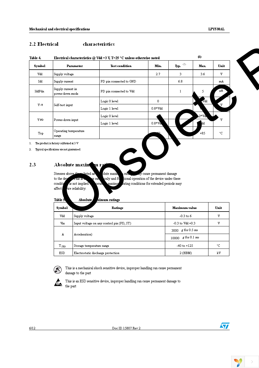
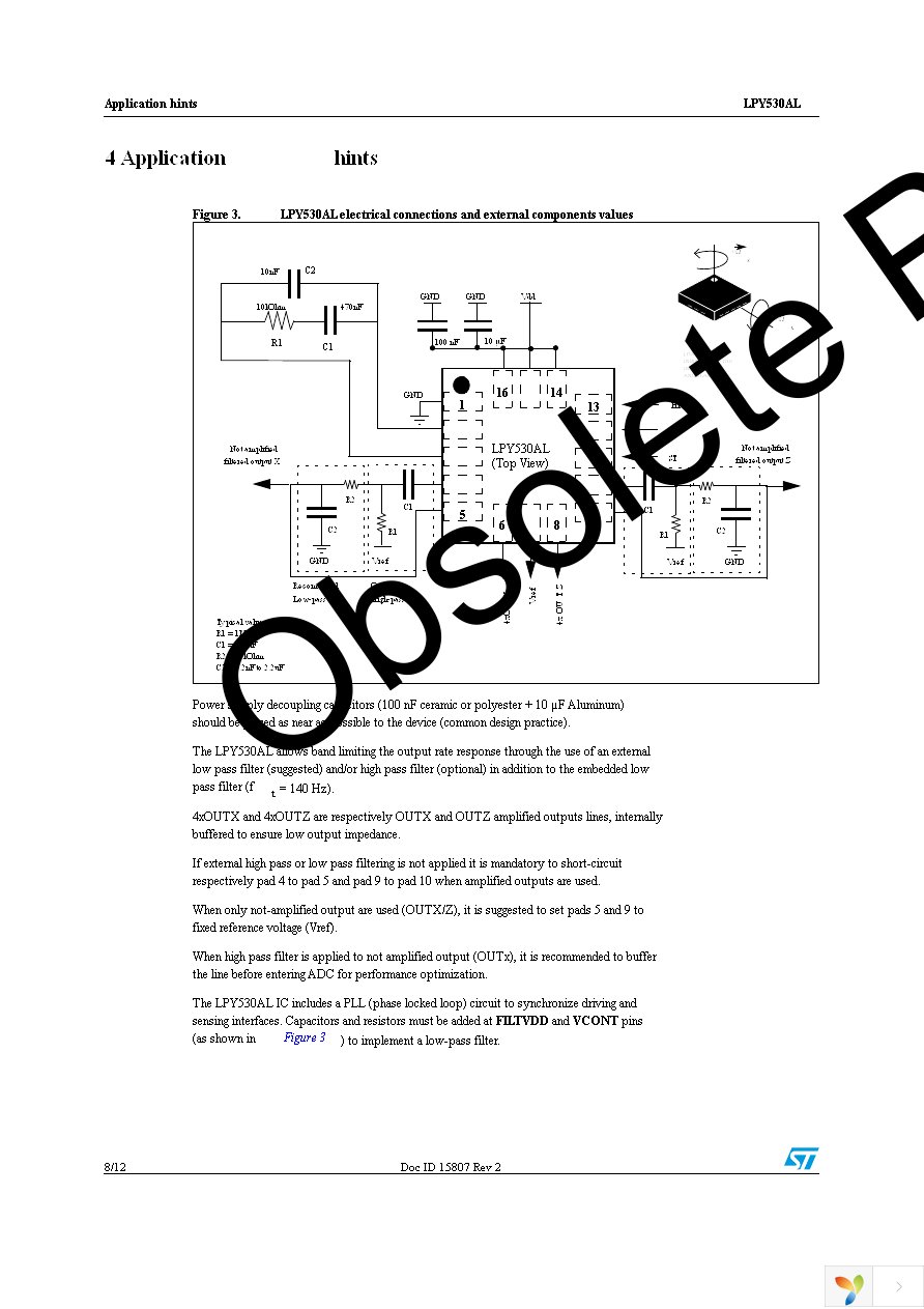
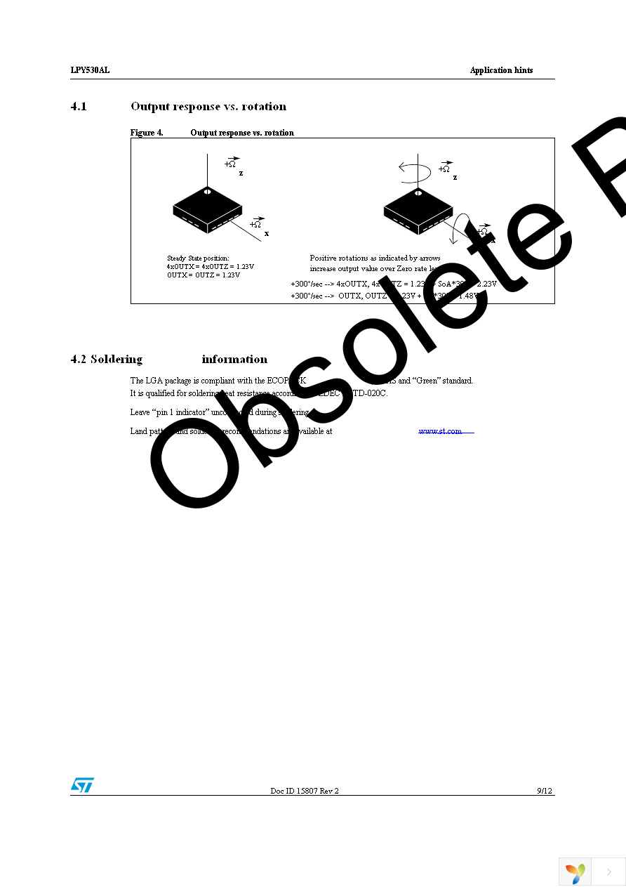
STEVAL-MKI037V1 Datasheet
P1
P2
P3
P4
P5
P6
P7
P8
P9
P10
P11
P12
Top
Sign in
Sign up
×
Email address
Please provide a valid email address.
Password
Show password
Remember me
Forgot password?
Sign in
Full name
Please fill in your name.
Email address
Please provide a valid email address.
Password
Show password
Confirm password
Show password
Sign up